- About us
-
Product
- Services
- Download
- Press center
- Contacts
TIK-RVM extended monitoring system for GPU
General block diagram of TIK-RVM extended vibration monitoring system for GPU

Measurements of the vibration parameters of the drive GTU are carried out by sensors - accelerometers, placed on the outer casing of the turbine near the main sources of vibration - the supports of the engine rotors, the blade, the combustion chamber, the drive box, as well as the area of the engine suspension supports to the frame. During the operation of mechanical equipment, the resulting vibrations are transmitted to the sensor housing, which generates a low-current signal proportional to the level of vibration acceleration.
Control of the centrifugal compressor of natural gas is carried out by measuring the position of the rotor relative to the fixed housing with the help of eddy current displacement sensors that generate a signal proportional to the air gap between the sensor end and the rotor shaft.
Signal amplification from accelerometers and eddy current sensors is realized by secondary transducers grouped in a switching box. The converters do not require separate power lines and are connected to the controllers by standard twisted pairs.
Sensors and transducers are manufactured in accordance with the requirements of application in harsh operating conditions, including placement in explosive zones 0 and 1 according to GOST 30852.9-2002 in a wide temperature range.
Filtered and amplified signals from the measuring channels are collected at the input of the measuring equipment, where they are normalized, digitized, compared with the current settings, as well as the collection of instantaneous values in the data package on demand of the expert system for further in-depth analysis. The measuring equipment generates adjustable discrete signals of alarm levels, converts the measured vibration signals into a standard range of 4-20 mA, implements data transmission interfaces.
Application diagram of TIK-RVM extended vibration monitoring system for GPU

Recommend to watch
New products
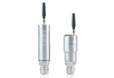
 TIK-WST temperature transducer
 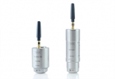 TIK-WSV vibration meter
 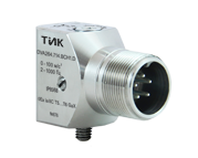 New product!


- Certified Laboratory of non-Destructive Testing in the field of vibrodiagnostics and visual-measuring control (VD and VMC)
- Training Center for training and advanced training of technical specialists
- Full production cycle from preparation to finished product
- Certified Metrological Service
- Complete Service Center