- About us
-
Product
- Services
- Download
- Press center
- Contacts
TIK-RVM extended monitoring system
General block diagram of TIK-RVM extended vibration monitoring system

At the level of primary transducers - vibration acceleration, vibration velocity sensors, DVA and IKV-1-x series displacement sensors are used, as well as any standard vibration transducers with a unified type of output signal. All vibration sensors supplied as part of the TIK-RVM system have a degree of protection against external influences IP66, and can also be equipped with a detachable connection at the customer's request to facilitate repair, maintenance and metrological maintenance. Vibration acceleration sensors have a frequency range from 10 to 10 000 Hz, which allows using the measuring channel for spectral diagnostics.
At the level of logic controllers as the base element using a programmable controller, TIK-PLC 241 ver.02.
It is a high-performance controller with a large number of interfaces that performs the functions of sensor polling, mathematical processing of the measured signal and the issuance of control and information signals to external devices and systems. In addition to the main functions, the controller provides power to two-wire sensors and performs the functions of a spark protection barrier. TIK-PLC has analog inputs 4-20 mA and ICP, groups of relay contacts, digital interfaces RS-485 and Ethernet. Programming of the controller is carried out in the language of the top level, which allows you to quickly reconfigure its internal logic for changing requirements and tasks.
Each measuring channel operates completely independently of the others. The fault tolerance of the system components supposes the output of signals to the equipment stops only in case of exceeding the level of vibration on several channels.
At the top level - arm diagnostician / arm operator - is an industrial workstation with installed SCADA-package and specialized modules (arm diagnostician).
The software of the TIK-RVM system performs the following functions:
- display of object mimic diagram with current values of measured parameters;
- event logging;
- registration and storage of parameter changes (trends);
- running a fast sample for spectral analysis;
- calculation and visualization of signal spectra;
- protection against unauthorized access;
- distribution of access rights for different groups of users;
- notification of personnel about emergency and warning situations.
On a separate order, it is possible to add the functions of automatic diagnostics, predicting the output of the unit to repair, assessing the quality of repair, remote control of the system, distributed use.
There is a possibility to use the software remotely over a local network or the Internet.
Composition of the crate


The power supply module (PSM) converts AC or DC voltage to DC or stabilized supply voltage of the functional modules (+24V, + 6V, 5V).
Is installed in slot №1.
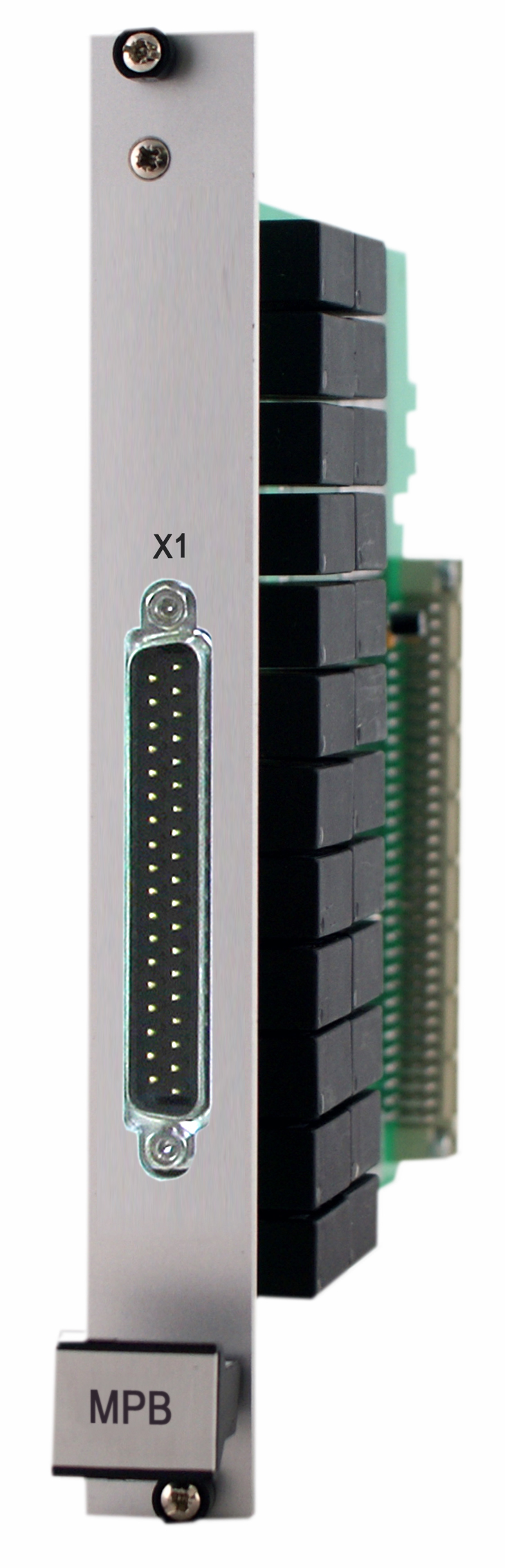
The relay output module (ROM) contains 12 dual relay channels (each channel includes two output relays to ensure reliability) with seven normally open and five normally closed contact groups. On the front panel of the module there is a 24-pin connector for external circuits.
Is installing in slot №2.
The module of discrete inputs and interface RS-485 (MDI) is intended for reception of external discrete signals. Also, the module is designed to connect an external digital interface RS-485 (Modbus-RTU exchange Protocol). All the electronics of the digital interface is in the module MI. This module also contains a non-volatile system time generator.
Is installing in slot №3.

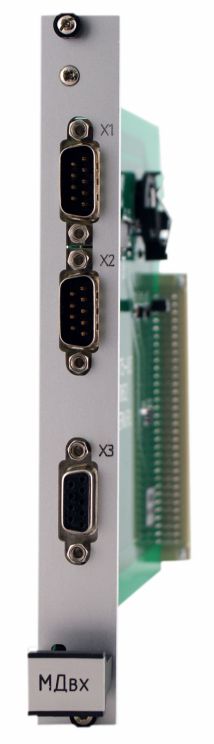
The analog output module (AM-14) is designed to transmit the following values to external automation and registration systems measured by TIK-PLC 241 ver.02 controllers:
- instantaneous values of vibration acceleration;
- vibration velocity RMS (4-20 mA);
- axial displacement;
- the signal from the sensors with the output 4-20 mA, current signal 4-20 mA.
Is installing in slot №4.
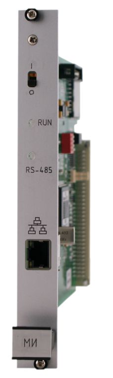
The interface module (IM) provides:
- ollection and storage of measurement data (vibration velocity, instantaneous values of vibration acceleration, axial displacement, input current) produced by TIK-PLC controllers;
- processing of discrete inputs;
- control of relay outputs;
- torage in non-volatile memory of the settings necessary for the operation of the crate;
- data exchange via digital communication interfaces (Ethernet, RS-485).
It is possible to make a "hot" module replacement without failures in the system. To ensure redundancy, the crate contains two IM.
Is installing in slots №5,6 (main, reserve).
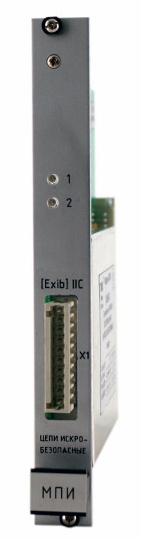
The intrinsically safe power supply module (ISPSM) is designed to supply USO MV-6/MS-6. The module contains two independent supply channels with a voltage of ±6.8 V with a load capacity of ±25mA each. The accuracy of the output supply voltage over the entire load range ±5%.
It is installed from 7 to 20 slots inclusive.
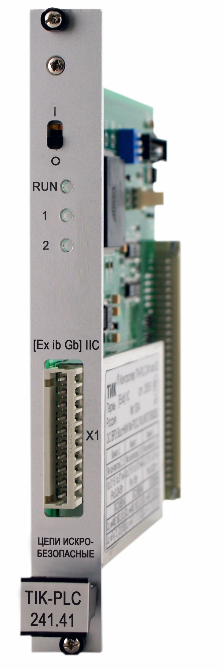
The controller TIK-PLC 241 ver. 02 is designed for registration and processing of received signals from primary converters. In addition, the controller performs the function of spark protection barrier and sensor power supply. The controller has a function of issuing signals exceeding the warning and emergency levels, as well as masking the channels to delimit the access of personnel.
Controllers are installed in the basket in the number of up to 14 pieces in slots from 7 to 20 inclusive. The number of controllers is determined by the required number of measuring channels in the system. To ensure that the sample is collected from multiple system crates, a synchronization module (SM)is installed instead of one of the controllers - so the system can scale.
APPLICATION DIAGRAM OF TIK-RVM SYSTEM TO THE RESPONSIBLE UNITS MONITORING

APPLICATION DIAGRAM OF TIK-RVM SYSTEM FOR CONDITION CRITICAL UNITS MONITORING

APPLICATION DIAGRAM OF TIK-RVM SYSTEM FOR TESTING OF SUBMERSIBLE PUMPS IN THE TEST WELLS

Recommend to watch
New products
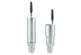
 TIK-WST temperature transducer
 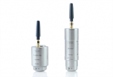 TIK-WSV vibration meter
 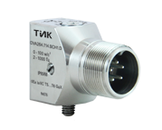 New product!


- Certified Laboratory of non-Destructive Testing in the field of vibrodiagnostics and visual-measuring control (VD and VMC)
- Training Center for training and advanced training of technical specialists
- Full production cycle from preparation to finished product
- Certified Metrological Service
- Complete Service Center